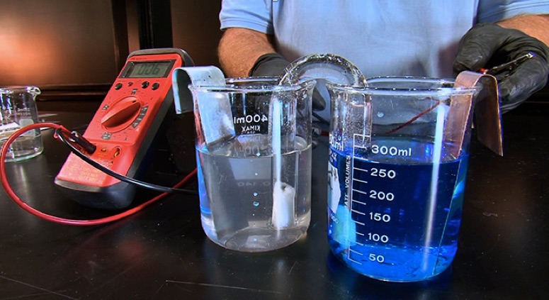
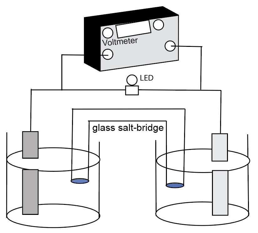
Demonstration of generating electricity from a chemical oxidation-reduction reaction. The process involves moving electrons. A standard cell comprising of two half-cells: zinc metal electrode in 1.0 M ZnSO4 solution, a copper metal electrode in a 1.0 M CuSO4 solution, and a connecting salt bridge. The electrodes in the half-cells are connected to a LED with a voltmeter measuring the emf of the cell across the resistance.
The cell reaction is Zn(s) + Cu2+(aq) --> Zn2+(aq) + Cu(s) E°cell = +1.10 Volts (direct current)
The voltage of the cell can be projected using a voltmeter or a Vernier LabPro interface.
Web page author: T. Greenbowe, University of Oregon. This page is under construction.
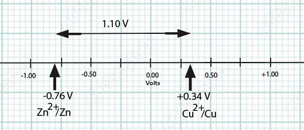
A Standard Zn/Cu Voltaic cell is used to show the E°cell generated is the difference in the standard reduction potentials between two half-reactions:
Consulting a Table of Standard Reduction Potentials
Cu2++ 2e- -> Cu E°(reduction) = +0.34 V
Zn2++ 2e- -> Zn E°(reduction) = -0.76 V written as reduction potentials for
Since zinc is a more active metal compared to copper, zince serves as the anode (see Activity Series of Metals Demonstration).
For a Zn|Zn2+||Cu2+|Cu electrochemical cell, we use reduction potentials to calculate the cell emf.
E°cell = E°reduction (cathode) - E°reduction (anode)
E°cell = +0.34 V - (-0.76 V) = + 1.10 Volts (direct current)
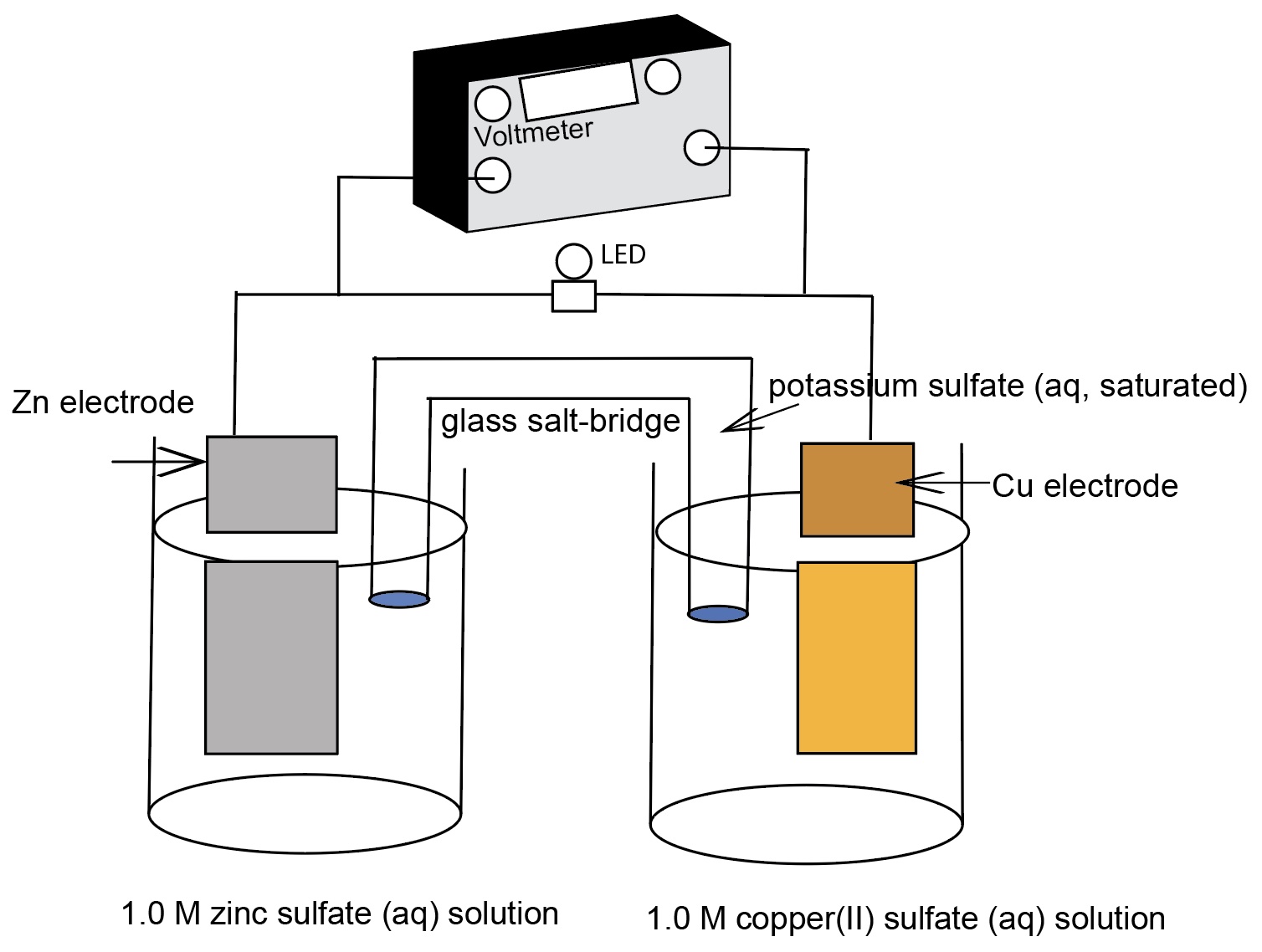
An extention to the demonstration. Ask students to predict the cell voltage if the size of the metal electrodes doubles and the volume of the aqueous solutions doubles (keeping the concentration at 1.00 M).
A diagram of a "normal size" zinc-copper electrochemical cell identifying the components of the cell.
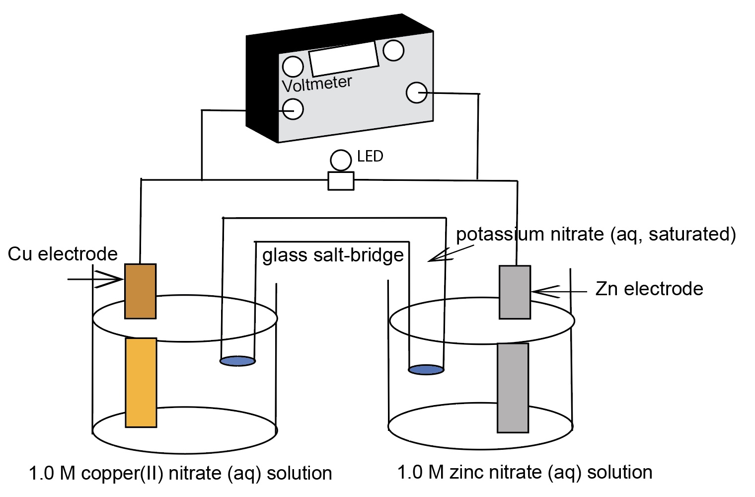
A larger zinc-copper electrochemical cell identifying the components of the cell. The zinc and copepr electrodes are twice the size and the volume of the solution is twice the size compared to the "normal size" ZnCu electrochemical cell. The cell voltage remains at +1.10 Volts.
50% of a class of students will predict the voltage doubles in the larger ZnCu cell. 30% of students will predict the voltage stays the same and 20% will not be confident in answering one way or the other.
Some Student Difficulties with Galvanic Cells (Electrochemical Cells) Addressed By Doing This Demonstration
1. Cell potentials are obtained by adding individual standard reduction potentials.
2. Cell potentials are influenced by the amount of material (mass, volume).
3. In an electrochemical cell diagram, the anode is always on the left.
4. Anodes, like anions, are always negatively charged and release electrons, and cathodes, like cations, are always positively charged and attract electrons.
5. The anode is positively charged because it has lost electrons. The cathode is negatively charged because it has gained electrons.
6. Electrons flow through the salt bridge and the electrolyte solutions to complete the circuit.
7. If the electrodes are connected to the voltmeter in such a way as to display a negative voltage, the flow of electrons is reversed.
8. A voltmeter measures the emf of an electrochemical cell.
Discussion
Due to a differences in electromotive force between zinc and copper, zinc is a more active metal compared to copper, a spontaneous oxidation-reduction process occurs when the zinc electrode is connected to the negative terminal and the copper electrode is connected to the positive terminal of the voltmeter. The spontaneous flow of electrons from anode (the zinc electrode) to cathode (the copper electrode) and the migration of cations and anions in the solutions and salt bridge generates a current with a voltage near the theoretical Eo cell = +1.10 V at room temperature.
Eo reduction (Volts)
Cathode Cu2+ + 2 e- → Cu + 0.34 V
Anode Zn2+ + 2 e- → Zn - 0.76 V Zinc is the more active metal
E° cell = E° reduction (cathode) - E° reduction (anode) = +0.34 V - (-0.76 V) = +1.10 V
When determining potential difference (emf) of electrochemical cells, we must take the difference between reduction potentials. This is why we compare reduction potentials.
Video Links
http://www.youtube.com/watch?v=A0VUsoeT9aM
http://www.youtube.com/watch?v=0oSqPDD2rMA
Materials
- Metal electrodes of the same size: magnesium, zinc, copper
- Metal electrodes of twice the size as above: magnesium, zinc, copper
- Aqueous solutions: 1.0 M MgSO4 solution, 1.0 M ZnSO4 solution, 1.0 M CuSO4 solution
- Voltmeter
- 4 400 mL beakers
- a salt bridge comprising a U-tube filled with 1 M KNO3 solution. The ends of the U-tube should be tightly plugged with cotton that has been saturated in the KNO3 solution.
- an empty 400 mL beaker to hold the salt bridge upright when not in use.
- Black and red wires with alligator clips
- Squirt bottle with deionized water
- Paper towels
- Lable tape, markers
- Steel wool, metal cleaning paper
- Document camera
Procedure
- Prefill the beakers with the 1.0 M solutions. Label the beakers.
- Place two beakers with solutions side by side.
- Place the regular size zinc electrode in the beaker containing 1.0 M zinc sulfate.
- lace the regular size copper electrode in the beaker containing 1.0 M copper(II) sulfate.
- Place the regular size zinc electrode in the beaker containing 1.0 M magnesium sulfate.
- Connect the black wire, using an alligator clip, to the top of the zinc metal electrode. Connect the other end of the black wire to the terminal of the voltmeter marked "ground".
- Connect the red wire, using an alligator clip, to the top of the copper metal electrode. Connect the other end of the red wire to the terminal of the voltmeter marked "lightning bolt".
- Place the salt bridge upside down so that one arm is one solution and the other arm in the other solution - connecting the solutions.
- Students should note that no voltage registers until the salt bridge is inserted into the solutions.
- Note the voltage.
- Students should complete the cell diagram. Identify ten things for an electrochemical cell.
- Ask students what will happen to the voltage if the size of the electrodes are doubled and the volume of the solutions are doubled?
- Replace the regular size electrodes with bigger sized electrodes. The voltage remains the same. Cell voltage does not depend on the size of the materials (mass, volume). However, cell voltage is influenced by the concentration of the solutions (see concentration electrochemical cells and Nernst electrochemical cells).
Safety Precautions
- Always wear goggles when performing chemistry demonstrations.
- Gloves should be worn to protect your hands from the solutions.
One day of lead time is required for this project.
Student electrochemical cell diagram
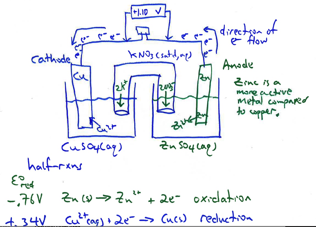
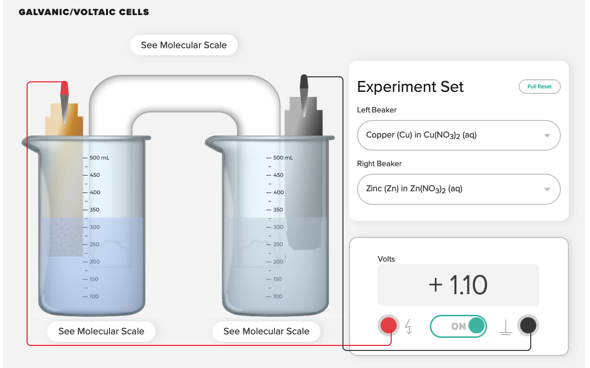
Pair this demonstration with computer animations showing a representation of the oxidation half-reaction occurring at the zinc anode and the reduction half-reaction occurring at the copper cathode.
ACS AACT voltaic cell computer simulation. Greenbowe, T.J.; Gelder, J.I., Boyd, A, Wixon, M. (2020). Galvanic/Voltaic Cells 1. American Association of Chemistry Teachers, American Chemical Society: Washington, D.C.
https://teachchemistry.org/classroom-resources/voltaic-cells (accessed April, 2023).
Curriculum Notes
Prior to doing these electrochemical cells demonstrations, it is recommended that the demonstration showing the reaction of magnesium with zinc sulfate, the reaction of zinc with CuSO4(aq) and the no reaction of copper with ZnSO4(aq) be shown and discussed. This is a great demonstration to re-introduce the concept of an activity series metals.

A guided-inquiry worksheet accompanies this activity. Download the file from the menu.
Students should conclude of the three metals, magnesium is the most active and copper is the least active. Order the metals in a vertical row with the least active metal on top
Cu least active metal
Zn
Mg most active metal
This order corresponds to the order of metals in a table of standard reduction potentials.
After presenting this demonstration, the standard hydrogen electrode demonstration can be used to show the SHE|H+,1.0 M |Cu2+,1.0 M |Cu cell and the Zn|Zn2+||H+,1.0 M| SHE cell.
The Voltmeter, Potentiometer and Physics.
There are two components to the flow of electrons that relate to the energy associated with an electrochemical cell:
Current (amps): The number of electrons flowing past a designated spot per second. An ammeter is used to measure current.
Potential or electromotive force (emf): The energy associated with each electron. The emf is the n"push" behind each electron.
The unit of the cell voltage, volt (V), is the energy per unit charge; 1 Volt = 1 Joule/Coulomb. A volt represents a joule of work per coulomb of charge.
When an electrochemical cell produces a current, the cell voltage is positive. Cell potential and work have opposite signs. A positive cell potential indicates how much electrical work a spontaneous reaction in a voltaic cell can do per unit electric charge moving though the circuit.
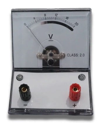 |  |
Voltmeters used to measure the voltage of electrochemical cells.
When the anode is connected to the black (-) terminal of the voltmeter using a black wire and the cathode is connected to the red (+) terminal using a red wire, the voltmeter will display a positive voltage. We use the chemists' view of current flow as electrons. In this view or representation, electrons are being pushed out of the anode and bump toward the negative terminal of the voltmeter. Electrons are being forced into the cathode. Simple voltmeters have the black terminal marked as "-" and the red terminal marked as "+". In multimeters, the black terminal is black in color and has the symbol "COM" for common. The red terminal is red in color and has a "lightning bolt" symbol or a "V".
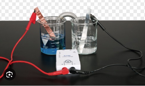
A PASCO voltmeter is used to measure the voltage of a zinc-copper voltaic cell. Note the zinc electrode, the more active metal, is connected to the negative terminal of the voltmeter using a black wire. The least active metal, copper is connected to the positive terminal of the voltmeter using a red wire.
Potentiometer
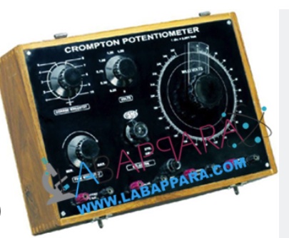
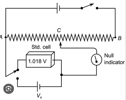
There is a problem using a voltmeter to measure voltage in an electrochemical cell. A voltmeter draws current from a cell due to internal resistance of the electrodes and wires and therefore will decrease the voltage. One cannot measure contact potential by using a contact probe (which is a voltmeter). One should use a potentiometer and a potentiometer circuit to measure the voltage of a cell. A potentiometer is an instrument for measuring voltage or 'potential difference' by comparison of an unknown voltage with a known reference voltage. If a sensitive indicating instrument is used, very little current is drawn from the source of the unknown voltage
 |  |
Reference: https://www.physicsforums.com/threads/understanding-the-role-of-a-voltme...
Reference: https://www.physicsforums.com/threads/understanding-the-role-of-a-voltme...
Reference: https://www.physicsforums.com/threads/understanding-the-role-of-a-voltme...
Reference: https://www.physicsforums.com/threads/understanding-the-role-of-a-voltme...
Reference: https://www.physicsforums.com/threads/understanding-the-role-of-a-voltme...
Computer animations for the Zn/Cu Voltaic cell beta versions (drafts)
Zn|Zn2+ oxidation half-reaction at the zinc electrode https://vimeo.com/220550690
Cu2+|Cu reduction half-reaction at the copper electrode https://vimeo.com/220550267
animation of the migration of ions in the salt-bridge https://vimeo.com/220548484
animation of the movement of electrons in a wire https://vimeo.com/220550589
Learning Objectives
1. Apply the Activity Series of Metals (and a Table of Standard Reduction Potentials) to help identify the more active metal in a voltaic cell.
2. Given a diagram of a simple electrochemical cell involving two metal electrodes and the corresponding solution of the metal ions identify: the site of oxidation reduction, the anode, the cathode, movement of electrons, migration of ions, the chemical equation representing the cell reaction.
3. Calculate the emf of a cell, given a table of standard reduction potentials and using the difference between reduction potentials method.
4. Draw a particle diagram representing the dynamic events occurring at each electrode and in the salt-bridge.
5. Cell voltage does not depend on the size (mass, volume) of matter - with respect to the electrode material or type of aqueous solution. Doubling the size of an electrode does not change the cell voltage. However, cell voltage does depend upon the concentration of each solution in the half-cells.
6. If a voltaic cell operates, the cell is producing electricity from an oxidation-reduction reaction. By definition the cell voltage is positive. If a voltmeter is reading a negative voltage, the leads need to be reversed to the electrodes.
AP Chemistry learning Objectives
3.12 The student can make qualitative or quantitative predictions about galvanic cell reactions based on half-cell reactions and electrode potentials.
3.13 The student can analyze data regarding galvanic cells to identify properties of the underlying REDOX reactions.
References
Abraham, M.; Gelder, J.; Greenbowe, T. (2007). During Class Inventions and Computer Lab Activities for First and Second Semester General Chemistry. Hayden-McNeil: Plymouth, MI.
Rahayu, S.; Treagust, D. F.; Chandrasegaran, A. L. (2021). High School and Preservice Chemistry Teacher Education Students’ Understanding of Voltaic and Electrolytic Cell Concepts: Evidence of Consistent Learning Difficulties Across Years. International Journal of Science and Mathematics Education. 1-24. https://doi.org/10.1007/s10763-021-10226-6
Sanger, M.J. and Greenbowe, T.J. (1997). “Student Misconceptions in Electrochemistry: Current Flow in Electrolyte Solutions and the Salt Bridge.” Journal of Chemical Education, 74(7), 819-823.
Sanger, M. J. and Greenbowe, T.J. (1997). “Common Student Misconceptions in Electrochemistry: Galvanic, Electrolytic, and Concentration Cells.” Journal of Research in Science Teaching, 34(4), 377-398.
Sanger, M.J. and Greenbowe, T.J. (1999). “An Analysis of College of Chemistry Textbooks as Sources of Misconception and Errors in Electrochemistry.” Journal of Chemical Education, 76(6), 853-860.
Shakhashiri, B. Z. In Chemical Demonstrations: A Handbook for Teachers of Chemistry; The University of Wisconsin Press: 1992; Vol. 4, p 101-106.
Yang, E.-M., Andre, T., Greenbowe, T. J., & Tibell, L. (2003). Spatial ability and the impact of visualization/animation on learning electrochemistry. International Journal of Science Education, 25(3), 329–349. https://doi.org/10. 1080/09500 69021 01457 38b
Old URL
The URL is http://introchem.chem.okstate.edu/DCICLA/voltaicCell20.html
