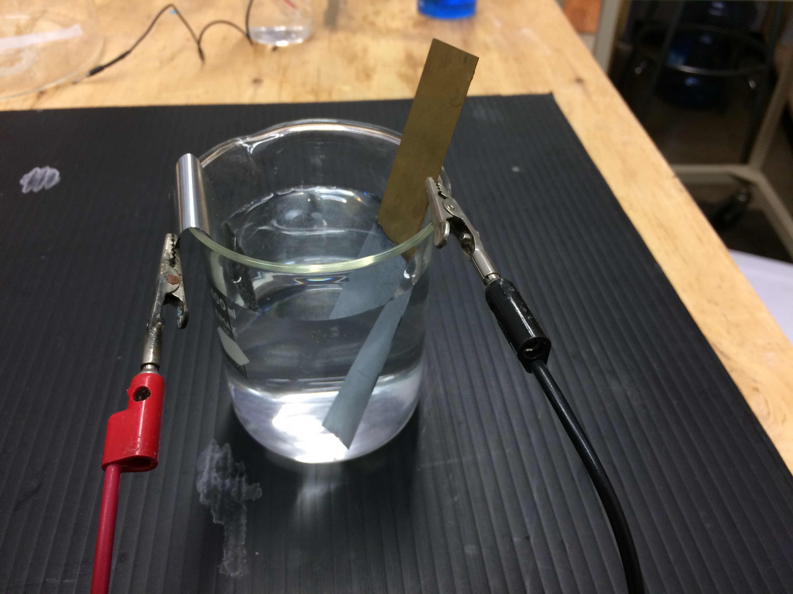
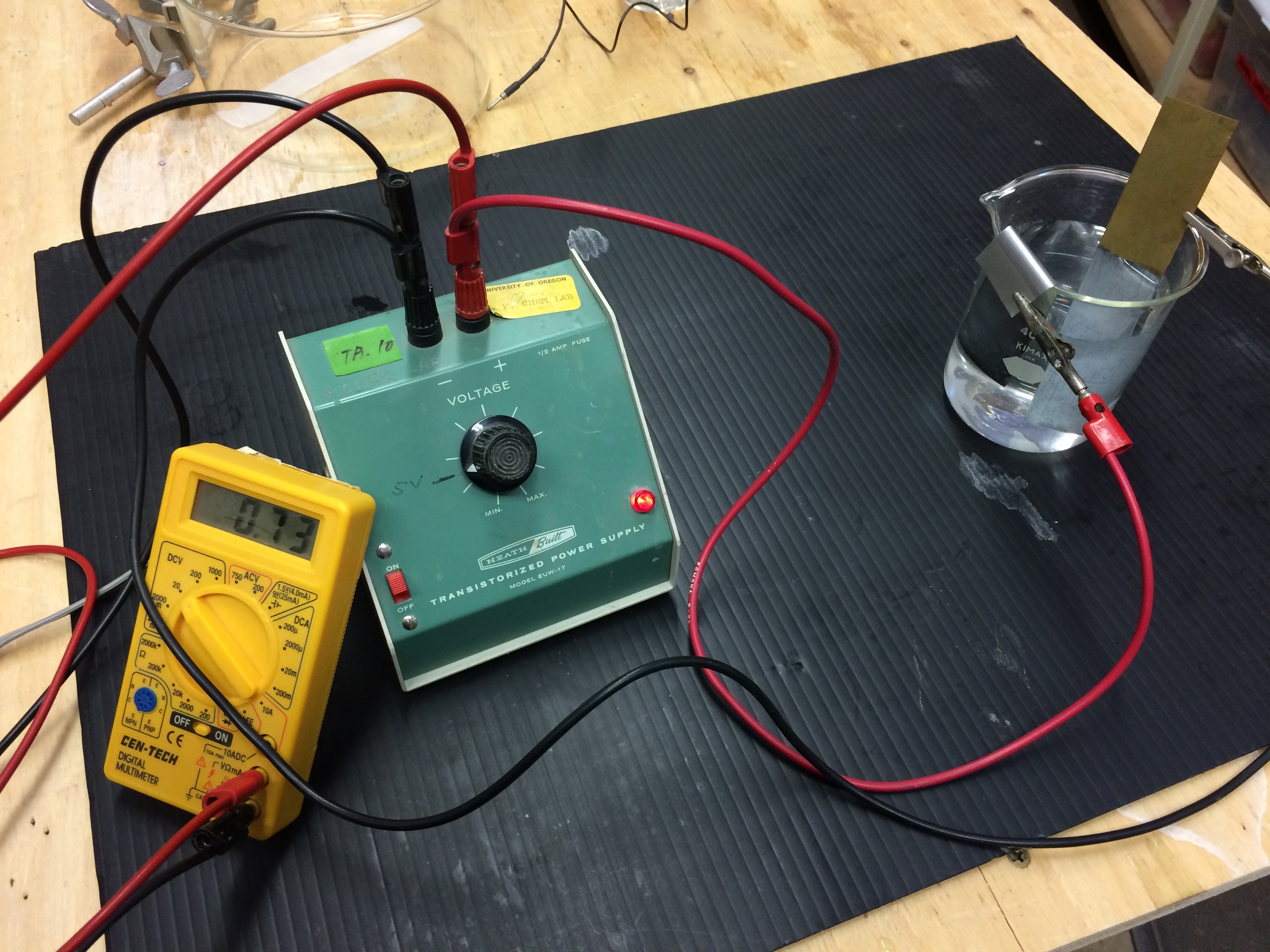
A zinc electrode and a copper electrode are placed in a beaker containing an aqueous solution of zinc sulfate, ammonium citrate, and ammonium chloride. The electrodes are connected to a DC power supply, the negative lead on the copper electrode and the positive lead on the zinc electrode. An ammeter is added to the circuit and used to measure the current. A stop watch is available and used to measure the time. A current is applied to the electrolysis cell. A white coating appears on the copper electrode almost immediately, and after a few minutes, the copper electrode has a definite zinc metal plating on it. This demonstration is an application of Faraday's Law. Electrolysis uses electrical energy to cause a nonspontaneous reaction (thermodynamically nonfavorable) to occur.
Web Page Co-Authors: T. Greenbowe and R. Sullivan , University of Oregon. This page is under construction.
One day of lead time is required for this project.
Instructors should start this demonstration with asking students if a chemical reaction occurs when copper metal is placed in aqueous zinc sulphate (or nitrate). The answer is no. Such a reaction is not spontaneous or not thermodynamically favorable. Cu(s) + Zn2+(aq) -> No reaction

Connecting the negative lead to the copper electrode supplies electrons to the copper electrode. The Zn2+ ions in solution near the copper electrode gain electrons to form zinc atoms, this is a reduction half-reaction. Metallic zinc coats the copper electrode. Electrolysis uses electrical energy to cause a nonspontaneous reaction (thermodynamically nonfavorable) to occur.
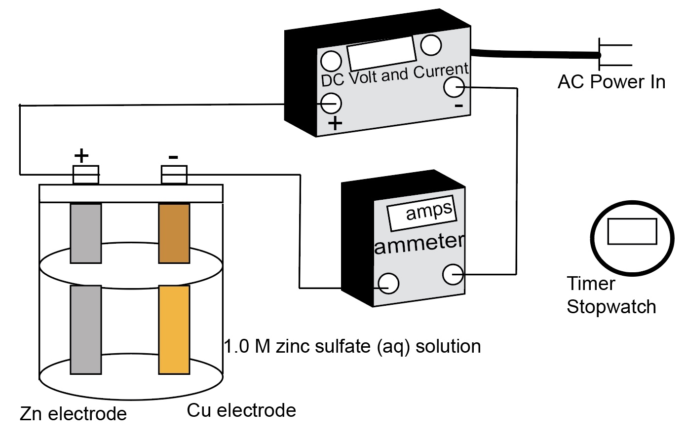

Zn2+(aq) + 2e- -> Zn(s), on the copper electrode. Reduction occurs at the cathode.
Connecting the positive lead to the zinc electrode removes electrons form the zinc electrode. The Zn atoms form Zn2+ ions
Zn(s) -> Zn2+(aq) + 2e- , on the zinc electrode. Oxidation occurs at the anode.
The Zn2+ ions generated at the anode replace the Zn2+ ions in solution being reduced to zinc atoms at the cathode.
The ammonium chloride improves conductivity, which allows us to plate rapidly at a low voltage. The ammonium citrate acts as a buffer to maintain acidic conditions.
Sample Data is displayed below.
Table 17.8 Sample Data and Results of Calculations of a Copper-Zinc Electrolysis Cell
Reduction Half-reaction | Current (A) | Time (s) | Moles e- | Moles Metal | Mass of Metal (g) |
Zn2+ + 2e- -> Zn | 8.00 | 900.0 | 0.0746 | 0.0746 | |
Zn2+ + 2e- -> Zn | 8.00 | 450.0 | 0.0373 | 0.0373 |
Materials
- 12 g ammonium citrate, (NH4)2HC6H5O7
- 7.5 g ammonium chloride, NH4Cl
- 30.0 g zinc sulfate heptahydrate, ZnSO4·7H2O
- ~300mL DI water
- zinc electrode
- copper electrode
- 400 mL beaker
- steel wool
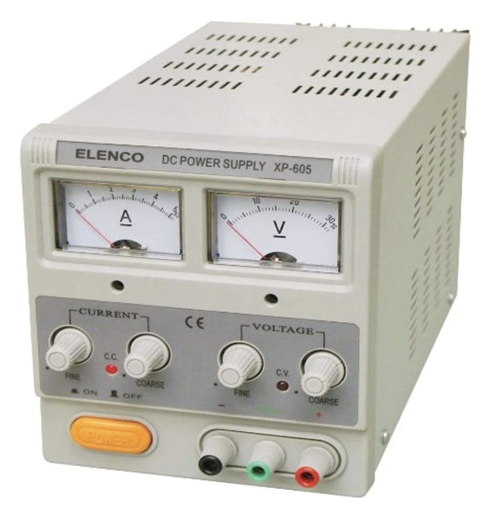
- DC voltage source with leads and alligator clips
- ammeter with leads
- timer
Procedure
- Place the electrodes in the beaker containing the plating bath. Be sure that the electrodes do not touch each other.
- Connect the DC power source to the electrodes and connect an ammeter in series in the circuit.
- Turn on the power source, adjust it to about 1 V, and let it run for 2-10 minutes. Record the current and time.
- Turn off the DC power source.
- Remove the copper electrode, dry it off with a paper towel, and buff it lightly with steel wool.
- Exhibit the plated electrode to the class.
Safety Precautions
- Wear goggles when performing this demo.
- Wear gloves when handling the wet electrode.
- Dispose of all chemicals appropriately.
Prep. Notes
The bath can be prepared by dissolving each of the solutes in about 300 mL of DI water in the 400 mL beaker.
The electrodes should be polished with steel wool and cleaned before being placed in the electrolysis cell.
Footnotes
This demo is a modification of "Galvanizing: Zinc Plating," from Bassam Z. Shakhashiri's Chemical Demonstrations, A Handbook for Teachers of Chemistry, v.4, (U. of Wisconsin, 1983) pp. 244-246.
Curriculum Notes
This demo can be used to illustrate a non-spontaneous electrochemical process when teaching a unit on electrochemistry: electrolysis. Have students predict which terminal of the DC Power supply the zinc metal electrode should be connected and which terminal to the DC Power Supply the copper electrode should be connected. The zinc electrode looses mass and the copper electrode gain mass. The mass lost at the zinc electrode is equal to the mass gained at the copper electrode, however drying and weighing the mass of each electrode is a bit time consuming during a lecture presentation. It can be done if the instructor provides the instruction and the lecture demonstrator presents the demonstration following the lead of the instructor.

Recommendations: Sequence of activities. Ask student to predict if the following reactions will occur or not and have the students offer an explanation: Cu(s) + ZnSO4(aq) --> ? and Zn(s) + CuZnSO4(aq) --> ? Calculate E°rxn for each possible reaction. After students predict and explain, show students a piece of copper metal placed in aqueous zinc sulfate results in "no reaction": Cu(s) + ZnSO4(aq) --> No Reaction. Show students the basic set-up for an electrolysis cell, but do not connect the metal electrodes. Have students decide which electrodes connect to which terminal of the D.C. Power Supply. A Class Activity or a POGIL Activity will have a diagram of the electrolysis cell with space for students to write in the parts of the cell and to show movement of electrons, ion migration, and half-reactions can accompany this demonstration. Use a clicker question to have students indicate the parts of the electrolysis cell and to identify the anode and cathode. It is recommended that this electrolysis demonstration be paired with the electrolysis simulation. The simulations will show a computer animation of a representation of the reduction half-reaction reaction occurring at the cathode copper electrode (Zn2+ + 2e- -> Zn) and the oxidation occurring at the anode zinc electrode (Zn -> Zn2+ + 2e-). The next lecture, Quiz questions can be used to assess students' understanding of basic electrolysis concepts and calculations. Two sample test questions assess students' conceptual understanding of electrolysis are posted.
The effectiveness of this Electrolysis Cell demonstration can be enhanced when it is accompanied by an electrolysis cell computer simulation and computer animation at the particulate level (atom level).
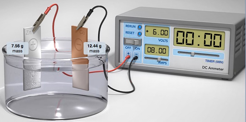
The Electrolysis Computer Simulation provides an opportunity to construct and experiment with several metal-metal electrolytic cells. Choose metal electrodes, electrolyte, current and time. The simulation shows the mass deposited at the cathode (and the mass lost at the anode) and animations at the particle level of what occurs at each electrode.
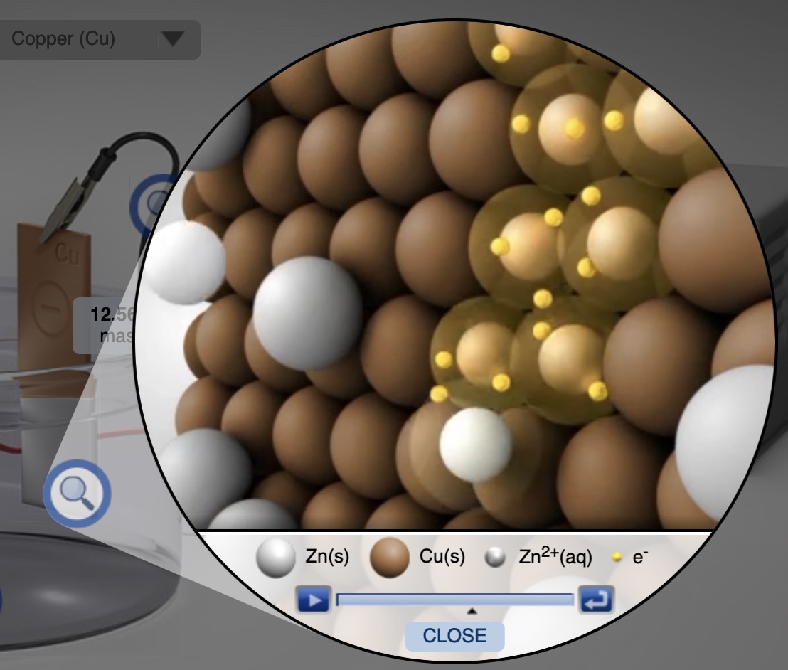
http://media.pearsoncmg.com/bc/bc_0media_chem/chem_sim/html5/Electro/Electro.php
Greenbowe, Abraham, Gelder Chemistry Education Instructional Resources ©2016. University of Oregon, University of Oklahoma, Oklahoma State University, Pearson.
A short segment of a particle level animation from the Electrolysis Simulation showing the reduction of Zn2+ ions to Zn atoms at the cathode (copper electrode).
It is helpful to show students a short animation of a representation of the movement of electrons in a simple DC circuit with a battery, bulb, and switch.
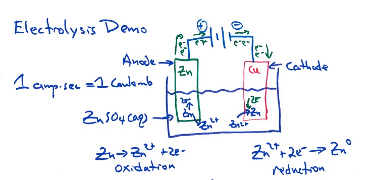
Student diagram of a ZnCu electrolysis cell
LEARNING OBJECTIVES After viewing the electrolysis demonstration and the accompanying computer simulation students should be able to:
1. Given an empty block diagram of a metal metal electrolysis cell, identify and or label the parts of an electrolysis cell: type of metal at each electrode, the movement of electrons going out of and into the D.C. Power Supply (or battery), the half-reactions occurring at each electrode, the anode, the cathode.
2. Select the terminal of a D.C. Power Supply or battery ("+" or "-") the electrode serving as the cathode should be connected. The metal will be deposited on which electrode?
3. Given the number of electrons "passed through" an electrolysis cell, determine and compare the number of metal ions reduced to metal atoms at the cathode. Students will compare M+, M2+, and M3+ cations receiving the same "charge" (same number of electrons).
4. Describe qualitatively how the time and current "passed through" an electrolysis cell influences the amount of metal deposited on the cathode (moles and mass), taking into account the charge of the cation.
5. Calculate the moles and mass of product deposited on a cathode of an electrolytic cell, given the half-reactions, time and current of the cell.
References
Gelder, J.I., Abraham, M.R., Greenbowe, T.J. (2015). “Teaching electrolysis with guided-inquiry.” In Sputnik to Smartphones: A Half-Century of Chemistry Education, M. Orna (ed.) ACS Symposium Series, Volume 1208, pp 141-154. American Chemical Society, Washington, D.C.
Greenbowe, T.J.; Gelder, John I.; Abraham, M.R. The Next Generation Project: Computer Simulations, Scenarios, Animations - Electrolysis. Pearson Education, Inc.: Upper Saddle River, NJ. (2015). http://media.pearsoncmg.com/bc/bc_0media_chem/chem_sim/electrolysis_fc1_gm_11-26-12/main.html
Sia, D., Treagust, D., Chandrasegaran, A. (2012). “High school students’ proficiency and confidence levels in displaying their understanding of basic electrolytic concepts." International Journal of Science And Mathematics Education, Dec, Vol.10(6), pp.1325-1345.
Sanger, M.J. and Greenbowe, T.J. (2000). “Addressing Student Misconceptions Concerning Electron Flow in Electrolyte Solutions with Instruction Including Computer Animations and Conceptual Change Strategies.” International Journal of Science Education, 22, 521-537.
Sanger, M.J. and Greenbowe, T.J. (1997). “Student Misconceptions in Electrochemistry: Current Flow in Electrolyte Solutions and the Salt Bridge.” Journal of Chemical Education, 74(7), 819-823.
Sanger, M. J. and Greenbowe, T.J. (1997). “Common Student Misconceptions in Electrochemistry: Galvanic, Electrolytic, and Concentration Cells.” Journal of Research in Science Teaching, 34(4), 377-398.
Shakhashiri, Bassam Z. "Galvanizing: Zinc Plating," Chemical Demonstrations, A Handbook for Teachers of Chemistry, v.4, (U. of Wisconsin, 1983) pp. 244-246.
Lee. R. Summerlin, Christie L. Borgford, and Julie B. Ealy, “Electroplating Copper,” Chemical Demonstrations, A Sourcebook for Teachers, Volume 2 (Washington: American Chemical Society, 1988), pp. 199−200. A stainless steel spoon is electroplated with copper in this demonstration.
