Use the Galvanic Cell Simulation to create a variety of galvanic/voltaic cells with different electrodes. Computer simulations of standard electrochemical cells comprised of two half-cells, a salt bridge and a voltmeter. Select different metals and aqueous solutions to build a galvanic/volatic cell that generates electrical energy from a chemical reaction. Use the cell potential from the voltmeter and data to determine the reduction potential of each half-reaction. Identify anode and cathode, write half-reaction equations and a full chemical equation. An animation provides a view of what is happening in each half-cell and in the salt bridge on a molecular scale - a representation at the particle level (Johnstone, 1993).
Metals: copper, zinc, magnesium, silver.
Aqueous 1.0 M solutions: copper(II) nitrate, zinc nitrate, magnesium nitrate, silver nitrate, hydrochloric acid
Standard hydrogen electrode
Web page author: T. Greenbowe, University of Oregon. This page is under construction.
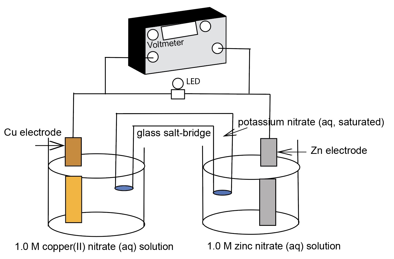
For example, zinc metal electrode in 1.0 M Zn(NO3)2 solution, a copper metal electrode in a 1.0 M Cu(NO3)2 solution, and a connecting salt bridge. The electrodes are connected to a voltmeter. E°cell = +1.10 Volts.

https://teachchemistry.org/classroom-resources/voltaic-cells
©2021 ACS Thomas Greenbowe University of Oregon, John Gelder Oklahoma State University, Adam Boyd AACT, Monica Wixon AACT: American Chemical Society, American Association of Chemistry Teachers: Washington, DC.
The following diagram identifies the components of a zinc-copper electrochemical cell.
This simulation is consistent with the Principles of Universal Design for learning in that multiple representations are incorporated in the presentation. This aimulation also provides an opportunity for students to make connections among the macroscopic, particle level, and symbolic levels of representation (Johnstone, 1982, 1991, 1993) associated with electrochemical cell processes. The AACT Galvanic Cell Simulation has particle level animations of what occurs at the surface of the electrodes, migration of ions in the aqueous solution, oxidation and reduction half-reactions, and migration of ions in the salt bridge.
For each electrochemical cell, students view an animation of what occurs at the surface of each electrode in a half-cell, in the solution, and in the salt bridge on a molecular scale (molecular scenes). The following animations provide a segment of the animations. Firefox 113.0.1 (64-bit) is working the best for playing the animations.
Students complete an electrochemical cell diagram. Identify the anode and cathode, write the half-reaction equations for each half-cell, a full chemical equation for the cell, identify movement of ions in the salt bridge and in the aqueous solutions, and show the movement of electrons in the wires and electrodes. Students also identify which electode is connected to the black terminal or the "ground" terminal (physics symbol for ground) and which electode is connected to the red terminal or "lightning bolt" or "V" terminal on the voltmeter.
 | 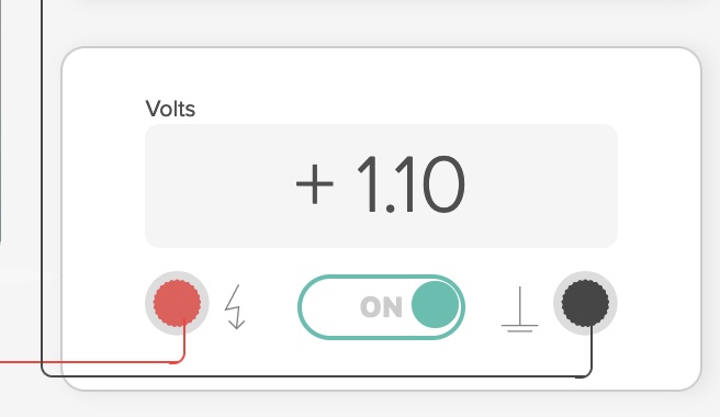 |
By definition, if an electrochemical cell is operating, meaning the cell is producing electricity from a chemical reaction, the cell potential is positive. If during a student experiment involving an electrochemical cell, a negative voltage is measured, the student needs to reverse the leads to the metal electrodes.
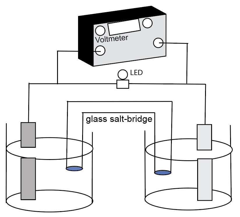
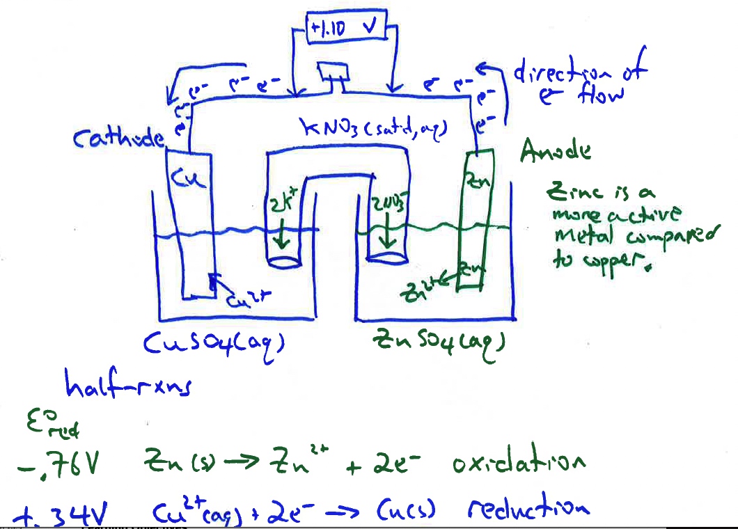
Two guided-inquiry worksheets are available to accompany this computer simulation. One is an AACT worksheet. Download the file from the ACS AACT web site. A modest yearly membership fee is required. The AACT membership fee helps to support building instructional resources.
Another worksheet by Abraham, Gelder & Greenbowe s available from the CIDER web site.
Curriculum Notes
Prior to doing these electrochemical cells demonstrations, it is recommended that the demonstration showing the reaction of zinc with CuSO4(aq) and the no reaction of copper with ZnSO4(aq) be shown and discussed. This is a great demo to introduce the concept of electrochemical cells. Pair this demonstration with computer animations showing a representation of the oxidation half-reaction occurring at the zinc anode and the reduction half-reaction occurring at the copper cathode.
Due to a differences in electromotive force between zinc and copper, zinc is a more active metal compared to copper, a spontaneous oxidation-reduction process occurs when the zinc electrode is connected the copper electrode and a salt bridge inserted. The spontaneous flow of electrons from anode to cathode and the migration of cations and anions in the solutions and salt bridge generates a current with a voltage near the theoretical Eo cell = +1.10 V at room temperature.
This potential is the driving force that pushes electrons through an external circuit. The emf of a cell is measured in units of Volts. The potential difference between two half-cells of an electrochemical cell is called the cell potential, Ecell.
Eoreduction (Volts)
Cathode Cu2+ + 2 e- → Cu + 0.34 V
Anode Zn2+ + 2 e- → Zn - 0.76 V
For a zinc-copper electrochemical cell the E° of the cell is determined by the difference between the two standard reduction potentials of the two half-cells
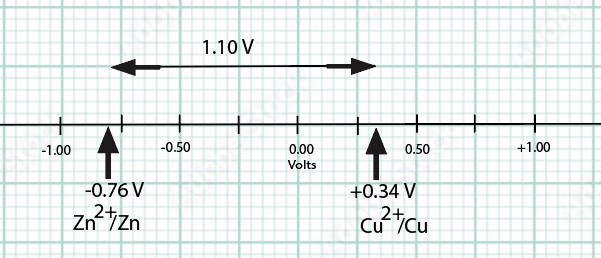
The electromotive force (emf) of the cell can be calculated by obtaining the difference in reduction potentials of the two half-cells.
E° cell = E° reduction (cathode) - E° reduction (anode) = +0.34 V - (-0.76 V) = +1.10 V
Concepts
- The potential difference or cell potential of an electrochemical cell depends upon
- the identity of the half-reactions occurring in each half-cell and
- the concentration of the ions in each of the solutions.
- if the concentration of ions in each solution is the same, the potential difference will be zero Volts.
- The standard potential difference, E° (voltage), does not depend upon the amount of material (volume of solution, size of electrodes) in the half-cells.
- The standard reduction potential, E°, in an electrochemical half-cell is an intensive property of matter when standard conditions of P= 1 atm, T = 25°C, and 1.00 M concentration of ions in solution apply.
- The potential difference of an electrochemical cell, E, under non-standard conditions is influenced by the concentration difference of the ions in the two half-cells.
1. Cell potentials are obtained by adding individual reduction potentials
2. Anodes, like anions, are always negatively charged and release electrons, and cathodes, like cations, are always positively charged and attract electrons.
3. The anode is positively charged because it has lost electrons. The cathode is negatively charged because it has gained electrons.
4. Electrons flow through the salt bridge and the electrolyte solutions to complete the circuit,
Learning ObjectivesReferences
Abraham, M.; Gelder, J.; Greenbowe, T. (2007). During Class Inventions and Computer Lab Activities for First and Second Semester General Chemistry. Hayden-McNeil: Plymouth, MI.
Greenbowe, T.J. (1994). An interactive multimedia software program for exploring electrochemical celIs. Journal of Chemical Education, 71(7), 555.
Sanger, M.J. and Greenbowe, T.J. (1997). “Student Misconceptions in Electrochemistry: Current Flow in Electrolyte Solutions and the Salt Bridge.” Journal of Chemical Education, 74(7), 819-823.
Sanger, M. J. and Greenbowe, T.J. (1997). “Common Student Misconceptions in Electrochemistry: Galvanic, Electrolytic, and Concentration Cells.” Journal of Research in Science Teaching, 34(4), 377-398.
Sanger, M.J. and Greenbowe, T.J. (1999). “An Analysis of College of Chemistry Textbooks as Sources of Misconception and Errors in Electrochemistry.” Journal of Chemical Education, 76(6), 853-860.
Sanger, M. J.; Greenbowe, T. J; Addressing student misconceptions concerning electron flow in aqueous solutions with instruction including computer animations and conceptual change strategies. International Journal of Science Education, 2000, Vol.22 (5), p.521-537.
Shakhashiri, B. Z. In Chemical Demonstrations: A Handbook for Teachers of Chemistry; The University of Wisconsin Press: 1992; Vol. 4, p 101-106.
de Jong O. and Treagust D. F., (2002), The teaching and learning of electrochemistry, in Gilbert J. G., de Jong O., Justi R., Treagust D. F. and van Driel J. H. (eds.), Chemical education: towards research based practice, Dordrecht: Kluwer, pp. 317-338.
Arevalo, Agustin; Pastor, Gloria; Verification of the Nernst Equation. Journal of Chemical Education, 1985, Vol.62 (10), p.882.
Garnett, P.J., Garnett, P.J. and Treagust, D.F.,"Implications of research on students’ understanding of electrochemistry for improving science curricula and classroom practice", International Journal of Science Education, 12 (2), 147-156, 1990.
Greenbowe, T.J.; Gelder, J.I., Boyd, A, Wixon, M. (2020). Galvanic/Voltaic Cells 2. American Chemical Society, American Association of Chemistry Teachers, Washington, D.C. https://teachchemistry.org/classroom-resources/galvanic-voltaic-cells-2
Johnstone, A.H. (1993). "The development of chemistry teaching: A changing response to changing demand. " Journal of Chemical Education, 70(9), 701-705.
Tro. N. Chemistry: A Molecular Approach (6th ed). 2022. Pearson: Hoboken, NJ.
Francisco J. Vidal-Iglesias, Jose Solla-Gullon,*Antonio Rodes, Enrique Herrero, and Antonio Aldaz. Understanding the Nernst Equation and Other Electrochemical Concepts: An Easy Experimental Approach for Students J.Chem.Educ. 2012, 89,936−939.
Michiel Vogelezang, and Adri Verdonk, “A Possible Electrochemical Route to a Thermodynamic Redox Reaction Equilibrium Constant in Secondary Education: An Attempt to Come from Science Fiction to Science Education?” World Journal of Chemical Education, vol. 8, no. 3 (2020): 128-140. doi: 10.12691/wjce-8-3-5.
